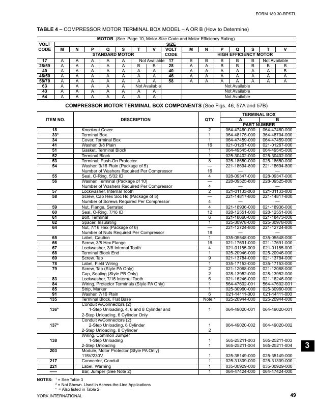

| Line | Part Number | Manufacturer | Request Quote |
|---|
| 1 | 364-48704-000 | York | Add to Quote |
| 2 | 228-09525 | York | Add to Quote |
| 3 | 025-31309 | York | Add to Quote |
| 4 | 064-49020-001 | York | Add to Quote |
| 5 | 025-20944-000 | York | Add to Quote |
| 6 | 021-14111 | York | Add to Quote |
| 7 | 021-17691 | York | Add to Quote |
| 8 | 025-18650-000 | York | Add to Quote |
| 9 | 021-16246 | York | Add to Quote |
| 10 | 025-31309-000 | York | Add to Quote |
| 11 | 025-30402 | York | Add to Quote |
| 12 | 064-47424-000 | York | Add to Quote |
| 13 | 025-20946 | York | Add to Quote |
| 14 | 025-30402-000 | York | Add to Quote |
| 15 | 221-14817-800 | York | Add to Quote |
| 16 | 025-20946-000 | York | Add to Quote |
| 17 | 021-13784 | York | Add to Quote |
| 18 | 064-49020-002 | York | Add to Quote |
| 19 | 221-12724-000 | York | Add to Quote |
| 20 | 021-16246-000 | York | Add to Quote |
| 21 | 064-47459-000 | York | Add to Quote |
| 22 | 021-01133 | York | Add to Quote |
| 23 | 221-12724-800 | York | Add to Quote |
| 24 | 028-09347-000 | York | Add to Quote |
| 25 | 025-20944 | York | Add to Quote |
| 26 | 064-49545-000 | York | Add to Quote |
| 27 | 021-01267-000 | York | Add to Quote |
| 28 | 021-01155 | York | Add to Quote |
| 29 | 021-13784-000 | York | Add to Quote |
| 30 | 221-14817-000 | York | Add to Quote |
| 31 | 025-18650 | York | Add to Quote |
| 32 | 064-49020-000 | York | Add to Quote |
| 33 | 021-17691-000 | York | Add to Quote |
| 34 | 021-01155-000 | York | Add to Quote |
| 35 | 021-01133-000 | York | Add to Quote |
| 36 | 064-47459 | York | Add to Quote |
| 37 | 028-09347 | York | Add to Quote |
| 38 | 064-47424 | York | Add to Quote |
| 39 | 064-49545 | York | Add to Quote |
| 40 | 021-01267 | York | Add to Quote |
| 41 | 021-14111-000 | York | Add to Quote |
| 42 | 021-18473 | York | Add to Quote |
| 43 | 565-25211-003 | York | Add to Quote |
| 44 | 035-17153 | York | Add to Quote |
| 45 | 025-35149 | York | Add to Quote |
| 46 | 064-47460 | York | Add to Quote |
| 47 | 021-18936-000 | York | Add to Quote |
| 48 | 364-48175 | York | Add to Quote |
| 49 | 025-35149-000 | York | Add to Quote |
| 50 | 025-30978 | York | Add to Quote |
| 51 | 021-18660-000 | York | Add to Quote |
| 52 | 028-12551-000 | York | Add to Quote |
| 53 | 025-30978-000 | York | Add to Quote |
| 54 | 028-13952-000 | York | Add to Quote |
| 55 | 028-13952 | York | Add to Quote |
| 56 | 565-25211-000 | York | Add to Quote |
| 57 | 021-12068-000 | York | Add to Quote |
| 58 | 021-18660 | York | Add to Quote |
| 59 | 564-47602-001 | York | Add to Quote |
| 60 | 028-12551 | York | Add to Quote |
| 61 | 035-00929 | York | Add to Quote |
| 62 | 025-30960-000 | York | Add to Quote |
| 63 | 364-48704 | York | Add to Quote |
| 64 | 564-47602-000 | York | Add to Quote |
| 65 | 035-05548 | York | Add to Quote |
| 66 | 025-30960 | York | Add to Quote |
| 67 | 228-09525-800 | York | Add to Quote |
| 68 | 021-12068 | York | Add to Quote |
| 69 | 064-47460-000 | York | Add to Quote |
| 70 | 021-18936 | York | Add to Quote |
| 71 | 035-05548-000 | York | Add to Quote |
| 72 | 565-25211-004 | York | Add to Quote |
| 73 | 035-17153-000 | York | Add to Quote |
| 74 | 221-18694-800 | York | Add to Quote |
| 75 | 364-48175-000 | York | Add to Quote |
| 76 | 035-00929-000 | York | Add to Quote |
| 77 | 021-18473-000 | York | Add to Quote |
| 78 | 221-18694-000 | York | Add to Quote |
