
| Line | Part Number | Manufacturer | Request Quote |
|---|
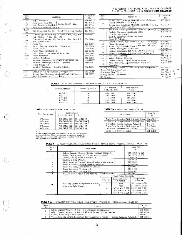
| 1 | 367-38892-000 | York | Add to Quote |
| 2 | 064-06119-000 | York | Add to Quote |
| 3 | 021-01447 | York | Add to Quote |
| 4 | 021-08898-000 | York | Add to Quote |
| 5 | 365-13975-000 | York | Add to Quote |
| 6 | 028-00824-000 | York | Add to Quote |
| 7 | 028-04754-000 | York | Add to Quote |
| 8 | 070-09705-000 | York | Add to Quote |
| 9 | 021-12307-000 | York | Add to Quote |
| 10 | 021-09932 | York | Add to Quote |
| 11 | 026-10797-000 | York | Add to Quote |
| 12 | 021-01435 | York | Add to Quote |
| 13 | 029-08659-000 | York | Add to Quote |
| 14 | 064-00296-000 | York | Add to Quote |
| 15 | 025-09980-000 | York | Add to Quote |
| 16 | 025-09981-000 | York | Add to Quote |
| 17 | 021-01372 | York | Add to Quote |
| 18 | 028-06791-000 | York | Add to Quote |
| 19 | 025-11046-000 | York | Add to Quote |
| 20 | 464-13364-000 | York | Add to Quote |
| 21 | 364-04119-001 | York | Add to Quote |
| 22 | 464-11965-000 | York | Add to Quote |
| 23 | 364-05384-000 | York | Add to Quote |
| 24 | 028-00867-000 | York | Add to Quote |
| 25 | 464-11962-000 | York | Add to Quote |
| 26 | 364-04119-000 | York | Add to Quote |
| 27 | 364-18963-000 | York | Add to Quote |
| 28 | 464-11963-000 | York | Add to Quote |
| 29 | 025-09421-000 | York | Add to Quote |
| 30 | 364-20993-000 | York | Add to Quote |
| 31 | 364-09881-000 | York | Add to Quote |
| 32 | 364-04115-001 | York | Add to Quote |
| 33 | 364-04115-000 | York | Add to Quote |
| 34 | 364-04121-001 | York | Add to Quote |
| 35 | 464-13366-000 | York | Add to Quote |
| 36 | 365-03256-000 | York | Add to Quote |
| 37 | 464-11964-000 | York | Add to Quote |
| 38 | 064-00314-000 | York | Add to Quote |
| 39 | 364-04122-000 | York | Add to Quote |
| 40 | 029-04452-000 | York | Add to Quote |
| 41 | 464-13362-000 | York | Add to Quote |
| 42 | 028-05175-000 | York | Add to Quote |
| 43 | 028-00869-000 | York | Add to Quote |
| 44 | 064-06648-000 | York | Add to Quote |
| 45 | 065-03233-000 | York | Add to Quote |
| 46 | 364-04117-001 | York | Add to Quote |
| 47 | 365-03238-000 | York | Add to Quote |
| 48 | 064-64363-000 | York | Add to Quote |
| 49 | 364-10084-000 | York | Add to Quote |
| 50 | 464-11961-000 | York | Add to Quote |
| 51 | 364-04122-001 | York | Add to Quote |
| 52 | 364-04117-000 | York | Add to Quote |
| 53 | 464-13365-000 | York | Add to Quote |
| 54 | 364-20991-000 | York | Add to Quote |
| 55 | 364-04123-001 | York | Add to Quote |
| 56 | 364-04121-000 | York | Add to Quote |
| 57 | 364-04123-000 | York | Add to Quote |
| 58 | 364-04114-000 | York | Add to Quote |
| 59 | 029-03669-000 | York | Add to Quote |
| 60 | 464-13363-000 | York | Add to Quote |
| 61 | 029-00274-000 | York | Add to Quote |
| 62 | 364-20992-000 | York | Add to Quote |
| 63 | 364-04116-000 | York | Add to Quote |
| 64 | 367-39035-000 | York | Add to Quote |
| 65 | 364-04114-001 | York | Add to Quote |
| 66 | 021-08899-000 | York | Add to Quote |
| 67 | 064-00751-000 | York | Add to Quote |
| 68 | 364-00364-000 | York | Add to Quote |
| 69 | 029-01507-000 | York | Add to Quote |
| 70 | 064-00360-000 | York | Add to Quote |
| 71 | 064-64362-000 | York | Add to Quote |
